Welcome to Vbond
How Improper Router Settings Ruin Aluminum Composite Panel Fabrication
How Improper Router Settings Ruin Aluminum Composite Panel Fabrication
You have received a shipment of premium aluminum composite panels. The aluminum composite panel manufacturer‘s technical specifications are clear. Your fabrication team begins routing V-grooves for folding. Then disaster strikes: the aluminum skin cracks along the bend line. The panel is scrap. Another panel shows rough, jagged edges. A third panel has melted core material oozing from the groove.
The culprit is almost always improper router settings.
Routing is the most critical—and most frequently mishandled—fabrication step for aluminum composite panels (ACPs). An ACNC router that is too fast, a bit that is worn, or a spindle speed that is too low can transform a high-quality ALUCOBOND manufacturer panel into expensive scrap in seconds. Understanding the delicate balance of router settings is essential for any procurement professional or fabrication manager working with ACPs.
This guide explains how improper router settings damage ACPs, provides the specific parameters required for clean routing, and outlines the quality control measures that prevent costly fabrication failures.
1. The Science of Routing ACPs: A Delicate Balance
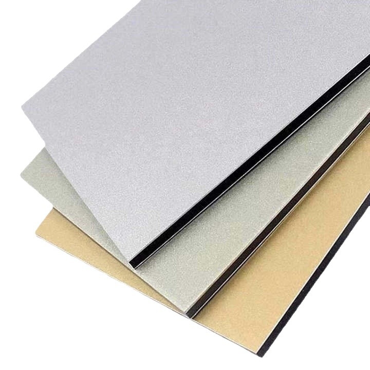
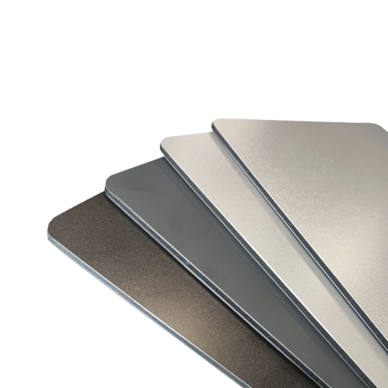
An aluminum composite panel is a sandwich structure: two thin aluminum skins (typically 0.3-0.5mm thick) bonded to a core material (polyethylene, FR, or A2 mineral). Routing a V-groove requires cutting through the bottom aluminum skin and part of the core while leaving the top aluminum skin intact to serve as a hinge for folding.
This is a precise operation. The depth tolerance is measured in tenths of a millimeter. The wrong settings create a cascade of failures:
Improper Setting | Immediate Consequence | Long-Term Damage |
Spindle speed too low | Foam core melts; aluminum tears | Burnt edges; weakened core; coating discoloration |
Feed rate too high | Rough edges; bit deflection; chatter marks | Poor folding surface; stress risers leading to cracking |
Spindle speed too high | Foam core melts; aluminum tears | Burnt edges; weakened core; coating discoloration |
Feed rate too high | Rough edges; bit deflection; chatter marks | Poor folding surface; stress risers leading to cracking |
Spindle speed too high | Aluminum burns; excessive dust | Heat-affected zone weakens the bond; coating damage | |
Incorrect bit angle | Groove too wide or narrow | Poor fold quality; visible edge after folding |
Worn or dull bit | Jagged edges; aluminum skin lifts | Delamination risk; inconsistent groove depth |
Groove too deep | The front aluminum skin is cracked or perforated | Catastrophic failure—panel cannot be used |
The Summa routing guidelines for ACPs specify that bits used for routing aluminum should not be used on other materials due to contamination. Similarly, AXYZ applications experts note that "replacing tips is cheaper than buying an entire new bit" when using V-grooving cutters with replaceable carbide tips.
2. The Critical Parameters: Getting Router Settings Right
2.1 Spindle Speed and Feed Rate
The relationship between spindle speed (RPM) and feed rate (speed of movement) determines cut quality. The recommended parameters vary by panel thickness and router type.
Standard Router (Universal Bit):
Panel Thickness | Bit Diameter | Passes | Feed Rate | Spindle Speed |
<4mm | 4mm | 1 pass | 80 mm/sec | 25,000 RPM |
>4mm | 4mm | Multi-pass | 80 mm/sec | 25,000 RPM |
High-Frequency Router:
Panel Thickness | Bit Diame | Passes | Feed Rate | Spindle Speed |
<4mm | 6mm | 1 pass | 120 mm/sec | 35,000 RPM |
<6mm | 6mm | 1 pass | 100 mm/sec | 35,000 RPM |
>6mm | 6mm | Multi-pass | 100 mm/sec | 35,000 RPM |
These parameters come from Summa's testing with ACP materials. "Higher speeds are possible but affect the quality of the edge," their guide warns. "If the speed is set too low, the foam will melt".
2.2 The Problem with Routing Too Slow
When the feed rate is too low or the spindle speed is too high for the material thickness, friction builds. The core material—especially polyethylene—melts and softens. This molten core material can:
- Clog the router bit, causing further friction and heat
- Leave a rough, uneven groove surface
- Weaken the bond between the aluminum skins and the core
- Create visible burn marks on the aluminum edge
One Summa technical note explains that "a cleaning pass is discouraged because the small offset may result in cracking of the lacquer on the aluminum sheets". Attempting to clean up a poor initial cut often makes the problem worse.
2.3 The Problem with Routing Too Fast
When the feed rate is too high or the spindle speed is too low, the bit cannot cut cleanly. Instead of shearing the aluminum, it tears. This creates:
- Jagged, rough edges along the groove
- Chatter marks from bit deflection
- Micro-cracks in the aluminum skin that propagate during folding
- Inconsistent groove depth across the panel length
The AXYZ technical guide recommends using "spiral fluted, carbide cutter" for profile cutting ACM panels, noting that these bits are "ground to provide optimum edge finish and tool life when running at relatively high cutting speeds".
3. V-Groove Geometry: The Flat Tip Advantage
One of the most overlooked aspects of ACP routing is the design of the V-grooving bit. Standard V-cutters produce a sharp point at the bottom of the groove. This creates a stress concentration point that often leads to coating cracking when the panel is folded.
The Solution: Use V-grooving bits with a small flat tip, typically 2-3mm across. The flat bottom of the groove distributes stress more evenly, significantly reducing the risk of paint cracking on the visible side of the panel during bending.
Tip Angles:
- For 90-degree folds, use a 110-degree bit to allow for springback
- For shallow folds, use 120-degree or 135-degree bits
The ALUCOLUX processing guide specifies that routing depth on a 3mm panel should be "ideally between 1.5mm and 2.3mm" to retain folding strength without cracking. For a 2mm panel, the ideal depth is "1mm to 1.3mm".
4. Core-Specific Considerations: FR vs. A2
Different core materials require different routing approaches. A reputable aluminum composite panel manufacturer, like an Alucobond factory** will provide core-specific processing guidelines.
FR Core (Fire-Retardant)
- Flexibility: Moderate
- Routing recommended: Standard V-groove bits acceptable
- Temperature sensitivity: Lower than A2; less prone to heat damage
- Multi-pass recommended: For panels >4mm thickness
A2 Mineral Core (Non-Combustible)
- Flexibility: Low (more brittle)
- Routing recommended: CNC required for precise depth control
- Temperature sensitivity: High—must avoid overheating
- Milling depth tolerance: Tighter than FR; ±0.05mm
The PREFABOND guide (a premium ALUCOBOND manufacturer brand) emphasizes that "V-groove cutting is only carried out with the aid of a CNC machine to ensure the correct milling depth" for A2 core panels. A2 mineral cores are less forgiving than FR cores; improper routing almost guarantees cracking.
Solid Aluminum Panels (ALUCOLUX)
For solid aluminum panels (non-composite), the routing requirements are different. ALUCOLUX is a "coil-coated solid aluminium panel" with a thickness of 2-3mm. These panels require:
- 3mm panel: routing depth 1.5-2.3mm
- 2mm panel: routing depth 1.0-1.3mm
Solid aluminum panels do not have a core, so there is no risk of core melting. However, the depth tolerance is equally critical—too deep, and the panel loses structural integrity; too shallow, and it cannot be folded.
5. The Multi-Pass Strategy
For thicker panels (>4mm), manufacturers recommend a multi-pass strategy rather than cutting the full depth in one pass.
The Problem with Single-Pass Deep Cuts:
- Excessive heat generation
- Bit deflection due to material resistance
- Increased risk of aluminum skin tearing
- Poor edge quality
The Solution: When routing in two passes, "make sure the first pass is in the bottom aluminum sheet; if not, the foam may melt". This means the first pass should cut through the bottom aluminum skin; the second pass completes the groove depth.
6. Common Routing Failures and Their Causes
Failure Mode | Visual Sign | Root Cause | Prevention |
Melted core | Burnt, oozing plastic in the groove | Feed rate too low; spindle speed too high; bit dull | Adjust speed; use a sharp bit; multi-pass |
Jagged edges | Rough, uneven groove surface | Feed rate too high; a bit dull | Reduce feed rate; replace bit |
Coating cracking | Fine cracks along the bend line after folding | Groove too deep; no flat tip on bit | Use a flat tip bit; reduce depth |
Chatter marks | Wavy pattern in the groove | Bit deflection; feed rate too high | Reduce feed rate; use shorter bit |
Inconsistent depth | Varying groove depth along the panel | Worn bit; uneven table; CAM settings | Replace the bit; calibrate the machine |
Aluminum skin perforation | Hole through the visible surface | Groove depth exceeded tolerance | Reduce depth; use CNC control |
A professional aluminum composite panel manufacturer will have documented these failure modes and provided prevention strategies in their processing manuals. The Aludecor quality framework, for example, tests "coating thickness, curing behaviour, and adhesion performance" at multiple stages to ensure that raw materials and finished products meet specifications.
7. Quality Control Before Routing
Before routing production panels, implement these quality control measures:
1. Verify Router Bit Condition
- Check for wear: Dull bits create heat and rough edges
- Dedicated bits: "Bits that have been used for routing aluminum should not be used on other materials."
- Clean bits: Remove debris between jobs
2. Test on Scrap Material
The ALUCOBOND processing guide explicitly states: "For serial production, please make tests on sample panels". Always run test cuts on scrap from the same batch before routing production panels.
3. Calibrate Groove Depth
- Use a micrometer to measure remaining material thickness
- For 3mm ACP, target 1.5-2.3mm depth, leaving 0.7-1.5mm of material
- Verify depth consistency across the table
4. Check Directionality
Some ACPs, particularly brushed finishes, have directional surface properties. The ALUCOBOND technical guide notes that "brushed finishes are directional" and "significant color variation will occur if panel directionality is not observed". While this affects final appearance more than routing success, it is still critical to maintain consistent orientation.
5. Monitor Temperature
For A2 mineral core panels, ensure the routing environment is ≥20°C. Cold panels are more brittle and prone to cracking.
8. How Professional Manufacturers Support Proper Routing
A reputable aluminum composite panel manufacturer, like an Alucobond factory or ALUCOBOND manufacturer, provides the technical documentation necessary for successful routing.
What to Expect from a Professional Manufacturer:
Documentation | What It Contains | Why It Matters |
Processing manual | Recommended tooling, speeds, feeds, depth specifications | Prevents guesswork |
Core-specific guidelines | FR vs. A2 routing parameters | A2 requires tighter control |
Test protocols | How to verify settings before production | Validates your setup |
Technical support* | Contact for troubleshooting | Saves time and material |
The ALUCOBOND brand, for example, provides detailed bending and routing guidelines for its composite and solid aluminum panels, including specific "FAQ" sections addressing fabrication questions.
The Aludecor 205-test framework includes "in-process quality checks" such as "pre-treatment quality checks on aluminium coils," "chemical conversion coating verification," "paint tinting accuracy and batch uniformity," and "core bonding consistency during lamination". These quality controls ensure that the panels arriving at your fabrication shop are consistent and predictable—but they do not replace correct router settings.
The Consequence of No Guidance
Suppliers who cannot provide processing documentation are likely selling commodity-grade panels with inconsistent mechanical properties. Without specifications, fabricators must guess. And guessing leads to cracked panels, melted cores, and wasted material.
9. Conclusion: Precision is Non-Negotiable
Improper router settings are not a minor inconvenience—they ruin aluminum composite panel fabrication. Melted cores, cracked coatings, and jagged edges are all preventable with the correct parameters.
For procurement professionals and fabrication managers, the requirements are clear:
1. Select a professional manufacturer that provides detailed processing manuals with core-specific routing parameters
2. Use the correct tooling—V-grooving bits with flat tips (2-3mm), not sharp-pointed cutters
3. Follow speed and feed guidelines—80-120 mm/sec feed rate; 25,000-35,000 RPM spindle speed
4. Route at the correct depth—For 3mm panels, depth 1.5-2.3mm; for 2mm panels, depth 1.0-1.3mm
5. Test on scrap before production—Never assume settings are correct
6. Use multi-pass for thick panels—>4mm requires two or more passes
7. Replace bits regularly—Dull bits create heat and poor edges
A professional aluminum composite panel manufacturer, like an Alucobond factory or ALUCOBOND manufacturer, will welcome these precautions. Their processing manuals provide the parameters you need. Suppliers who cannot provide documentation are likely selling commodity-grade panels with unpredictable behavior.
The best router setting is the one you test and verify before cutting your first production panel. Do not let improper settings turn premium panels into expensive scrap.