Welcome to Vbond
How to Design Expansion Joints for Aluminum Composite Panel Systems
For procurement professionals, a beautifully specified aluminum composite panel (ACP) facade is only as durable as its ability to move. Aluminum expands and contracts significantly with temperature changes—far more than steel, concrete, or masonry. Without properly designed expansion joints, this inevitable movement translates into buckled panels, cracked sealants, oil-canning distortion, fastener failure, and compromised weatherproofing. These failures not only void warranties but also lead to costly remediation, safety hazards, and reputational damage.
This article provides a comprehensive guide to designing expansion joints for ACP systems, from understanding thermal movement calculations to material selection, spacing guidelines, and integration with building codes—enabling procurement professionals to specify systems that move safely and last decades.
Part One: Why Expansion Joints Are Non-Negotiable for ACPs
The Physics of Thermal Movement
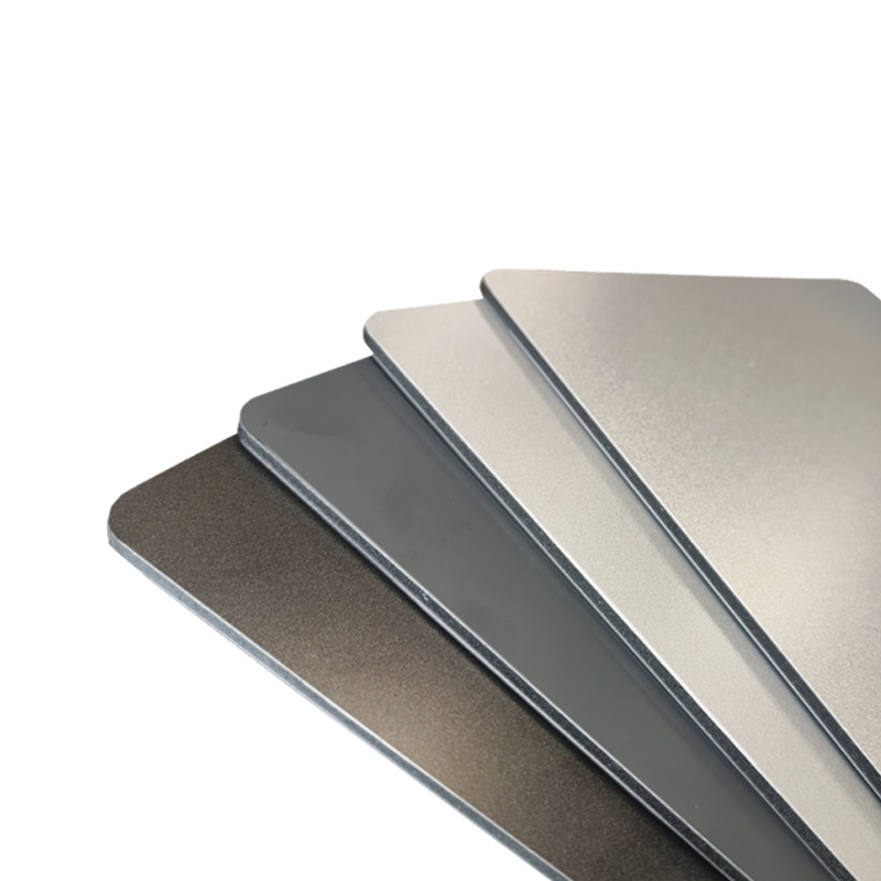
Aluminum composite panels consist of two thin aluminum skins bonded to a core—typically polyethylene (PE), fire-retardant (FR), or mineral-filled A2 material. Aluminum has a relatively high coefficient of thermal expansion: approximately 23 μm/m°C (0.000023 m/m°C) for solid aluminum, while the polyethylene core expands even more dramatically at 1.5×10⁻⁴/°C—nearly six times that of the aluminum skins.
This means an ACP panel changes length by approximately 2.3 mm per meter of panel length for every 100°C temperature difference. In practical terms, a 6-meter panel in a region with a 50°C seasonal swing (e.g., −10°C to +40°C) will expand by roughly 6 × 2.3 × (50/100) = 6.9 mm. Without room to move, that force transfers directly to fasteners, substructure, and adjacent panels—causing the visible “oil can” effect: wrinkles, ripples, or “waffling” on the exposed surface.
What Happens When Movement Is Restricted
When ACP panels are installed without allowance for thermal expansion—often pushed tight against each other—the results are predictable and costly. Thermal expansion may cause bending at the weakest parts of the panel, which are at the folds of the returns. Repeated expansion and contraction cycles open and close the fold repeatedly, potentially weakening the fold or allowing uncontrolled water penetration. As with any metal, repeatedly bending it eventually leads to fatigue and failure.
Failure to accommodate movement is a leading cause of premature facade deterioration, directly voiding most manufacturer warranties. Warranty provisions typically exclude “damage to the Product that occurs during its installation,” and improper expansion joint design is considered an installation error.
Part Two: Calculating Required Joint Width
The Fundamental Formula
The total expected movement of an ACP panel is calculated using the linear thermal expansion formula:
> ΔL = α × L × ΔT
Where:
- ΔL = change in length (mm or inches)
- α = coefficient of linear thermal expansion (for aluminum: 0.000023 m/m°C; for ACP assemblies, ≈ 0.000024 m/m°C is a safe design value)[reference:4][reference:5]
- L = initial panel length (mm or inches)
- ΔT = temperature change from installation to extreme conditions (°C)
Step-by-Step Calculation Example
A building in a continental climate with an installation temperature of 20°C and an extreme temperature range of −20°C to +40°C yields a ΔT of 60°C (from 20°C down to −20°C, plus from 20°C up to 40°C = 60°C total swing).
For a 4,000 mm (4 m) panel:
- Expansion in one direction = 0.000024 × 4000 × 20 = 1.92 mm (warming from 20°C to 40°C)
- Contraction in the opposite direction = 0.000024 × 4000 × 40 = 3.84 mm (cooling from 20°C to −20°C)
Total potential movement = 5.76 mm per panel edge.
Industry safety margin: Design the joint width to accommodate twice the calculated movement to account for installation tolerances, unforeseen temperature extremes, and long-term creep. The required joint width per edge is therefore 11.5 mm. This aligns with industry guidelines recommending expansion joints every 4–5 meters for metallic structures with a minimum gap of 3 mm between butt-joined sheets.
Practical Joint Width Guidelines
Panel Length | Calculated Movement (ΔT=60°C) | Recommended Joint Width (×2 safety factor) |
2,000 mm | 2.9 mm | 6–8 mm |
3,000 mm | 4.3 mm | 8–10 mm |
4,000 mm | 5.8 mm | 10–12 mm |
5,000 mm | 7.2 mm | 12–15 mm |
6,000 mm | 8.6 mm | 15–18 mm |
For high-temperature environments, such as desert climates with temperatures exceeding 50°C, a 3 m long panel may expand by as much as 11.25 mm from 25°C to 50°C, requiring significantly larger joint allowances.
Part Three: Expansion Joint Spacing and Location
General Spacing Guidelines
The spacing of expansion joints should be determined by the panel's expected movement and the substructure's ability to accommodate that movement. Industry practice recommends:
Panel Orientation | Recommended Joint Spacing | Justification |
Horizontal runs | Every 6–9 meters | Most common for facade elevations |
Vertical runs | Every 6–9 meters | Depends on building height and panel dimensions |
Perimeter at building corners | Perimeter at building corners | Corner zones experience higher wind and thermal stresses |
At changes in building geometry | Immediately | Transitions between different facade planes require separation |
For aluminum structures specifically, expansion joints are required at intervals not exceeding approximately 10 meters (32 feet) for aluminum components, with joints evenly spaced[reference:9]. In seismic zones, joint spacing may need to be reduced further, with movement joints every 2–3 meters incorporating neoprene or EPDM seals rated for extreme temperatures.
Strategic Joint Placement
Expansion joints should be located at:
- Natural building expansion points: Where the structural frame has expansion joints
- Floor lines: Horizontal joints at each floor slab to accommodate differential movement between stories
- Panel termination points: Where cladding meets windows, doors, or other materials
- Corners and re-entrant angles: Stress concentration zones
- Long, uninterrupted runs: Every 6–9 meters in both directions
- Changes in panel orientation or geometry: Transitions between flat and curved sections
Structural joints need to be continuous around the building enclosure, without any discontinuities or bridging of the joint, involving numerous materials, including roofing/waterproofing membranes, air/vapor barriers (AVBs), claddings, and floors.
Part Four: Fastener Systems That Allow Movement
Slotted and Oversized Holes
The most effective way to accommodate thermal movement at the panel-to-substructure connection is through slotted or oversized fastener holes combined with floating clip systems that allow panels to slide laterally as they expand and contract.
A three-dimensional adjustable hanger system allowing displacement compensation of ±5 mm, with spacing between fixed points ≤400 mm, is recommended for high-temperature environments. This approach secures panels firmly yet permits expansion and contraction without transferring stress to the panel or substrate.
Fixed vs. Sliding Connection Points
A fundamental principle of expansion joint design: one fixed point per panel, all others sliding.
Connection Type | Function | Application |
Fixed connection | Anchors panel at a single point, establishing zero-movement reference | Center of the panel or at one corner |
Sliding connection | Allows movement in one or two axes while maintaining attachment | All other fastener locations |
All other fastener locations | Provides multi-directional movement capacity | Concealed fastener systems |
A patented sliding clip technology allows for expansion and contraction in all four directions, eliminating potential oil-canning or waviness. The industry-standard Arrowhead Panel Installation System has been designed, engineered, and tested to safely allow for thermal expansion and contraction.
Fastener Torque and Installation
Proper torque control is essential. Self-tapping screws should be made of 316 stainless steel, with torque controlled at 1.5–2.0 N·m. Overload will cause the plate to collapse and deform[reference:16]. A step-by-step construction method is recommended: pre-tighten fasteners to 70% strength first, then fully tighten after 24 hours, allowing the assembly to settle before final torquing.
Part Five: Sealants and Backer Rods for Expansion Joints
Movement Capacity Requirements
Expansion joint sealants must accommodate the calculated joint movement while maintaining a waterproof and airtight seal. For ACP facades, specify sealants with:
- Movement capacity of ±25% to ±50% of original joint width
- Low modulus (soft and flexible, not stiff)
- UV resistance for exterior exposure
- Neutral cure (no acetic acid release, which corrodes aluminum)
Hybrid polymer sealants, such as MS-Polymer-based products, offer superior flexibility (±50% movement), excellent UV and weathering resistance, and strong adhesion to aluminum without yellowing. Silicone sealants specifically formulated for aluminum composite panel facades are also suitable, particularly where a matte finish is required.
Backer Rod Selection
Closed-cell polyethylene backer rods must be used behind all sealant applications to:
- Control sealant depth (optimal width-to-depth ratio of 2:1)
- Provide a bond-breaking surface (preventing three-sided adhesion)
- Absorb movement without extruding sealant
Critical rule: Never use open-cell foam backer rods in exterior expansion joints, as they absorb water and lead to sealant failure.
Part Six: Fire Barriers in Expansion Joints
Expansion joints that penetrate fire-rated assemblies must incorporate fire barriers to prevent the spread of flame, smoke, and toxic gases. These joints need to accommodate movement while providing a tested fire-resistance rating.
The three common types of fire barrier expansion joint systems are:
System Type | Description | Application |
Compression systems with mineral wool | Fire-resistant insulation compressed within the joint | Moderate movement, economical |
Fire-rated foams | Intumescent foams that expand when heated | Complex geometries |
Fire blankets | Flexible refractory fabric sheets spanning the joint | High-movement applications |
Fire barriers are required wherever the building's fire-resistance-rated construction is interrupted by an expansion joint. These systems must be tested to ASTM E2393 or equivalent standards and installed in strict accordance with manufacturer specifications. Failure to install approved fire barriers in expansion joints is a code violation that can void insurance coverage and result in substantial liability.
Part Seven: Material Compatibility and Dissimilar Materials
Aluminum-to-Aluminum Connections
Where ACP panels meet aluminum substructure, thermal expansion is similar (both have coefficients around 23 μm/m°C), minimizing differential movement. However, proper sliding connections remain essential.
Aluminum-to-Steel Connections
Steel has a coefficient of approximately 12 μm/m°C—roughly half that of aluminum[reference:21]. When aluminum panels are attached to steel substructure, the aluminum will expand and contract approximately twice as much as the steel over the same temperature range. This differential movement must be accommodated at every connection point using slotted holes, sliding clips, or flexible gaskets.
Interface with Other Materials
Material Pair | Coefficient Mismatch | Required Action |
ACP to glass | Glass: ~9 μm/m°C (aluminum ~23) | Use flexible gaskets; separate the joint |
ACP to concrete | Concrete: ~10–14 μm/m°C | Expansion joint with backer rod and sealant |
ACP to masonry | Masonry: ~5–8 μm/m°C | Dedicated expansion joint; no rigid connections |
When combining materials with different coefficients of thermal expansion, the transition must be detailed carefully—mismatched CTEs cause differential movement and stress at joints.
Part Eight: Procurement Specifications for Expansion Joints
To ensure proper expansion joint design is not overlooked, incorporate these specifications into procurement documents:
Design Specifications
- Require thermal movement calculation based on project-specific ΔT (including surface temperature effects for dark colors)
- Specify minimum joint width based on calculation × safety factor (minimum 2×)
- Require expansion joints at intervals not exceeding 9 meters in any direction
- Specify one fixed point per panel with all other connections sliding
- Mandate slotted or oversized fastener holes for sliding connections
Sealant Specifications
- Specify neutral-cure silicone or MS-polymer sealant (no acetoxy-cure)
- Require movement capacity of ±25% minimum (±50% preferred for high-movement zones)
- Specify closed-cell polyethylene backer rod (no open-cell foam)
- Require UV and weathering resistance with documented test data
Fire Safety Specifications
- For expansion joints penetrating fire-rated assemblies, specify a tested fire barrier system
- Require ASTM E2393 or equivalent compliance
- Mandate third-party test documentation for all fire-rated joint systems
Part Nine: Common Design Errors and Their Consequences
Error | Consequence | Prevention |
Insufficient joint width | Panels buckle at joints under expansion; sealants compress beyond capacity | Calculate ΔL using project-specific ΔT; apply 2× safety factor |
No sliding connections | Stress transfers to fasteners and panel folds; oil-canning and fastener failure | One fixed point per panel; all others sliding |
Wrong sealant chemistry | Acetoxy-cure sealants corrode aluminum; sealant cracks under movement | Specify neutral-cure silicone or MS-polymer |
Open-cell backer rod | Water absorption leads to freeze-thaw damage and sealant failure | Closed-cell polyethylene backer rod only |
No fire barrier in rated joints | Fire spreads through the expansion joint void, violating code | Install a tested fire barrier system |
Inconsistent joint spacing | Uneven stress distribution; aesthetic inconsistency | Space joints evenly per the structural grid |
Conclusion
Expansion joints are not architectural afterthoughts—they are the engineered pathways that allow aluminum composite panel systems to survive decades of thermal cycling without failure. Without them, the inevitable expansion and contraction of aluminum converts into buckled panels, cracked sealants, oil-canning distortion, and potentially catastrophic fastener failure.
For procurement professionals, the message is clear: specify thermal movement calculations based on project-specific temperature ranges. Require expansion joints at intervals not exceeding 9 meters. Mandate slotted or sliding connection systems with one fixed point per panel. Specify neutral-cure, high-movement-capacity sealants with closed-cell backer rods. For fire-rated assemblies, require tested fire barrier systems.
Expansion joints may represent a small line item in the facade budget, but their omission or under-design represents a disproportionate risk. When you design for movement, you design for longevity. When you ignore movement, you invite failure.