Welcome to Vbond
Common Installation Mistakes to Avoid with ACP Panels: A Technical Analysis and Prevention Protocol
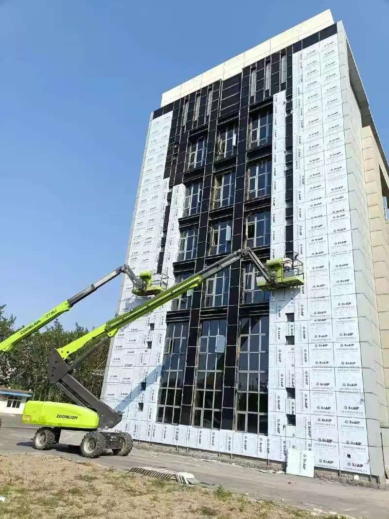
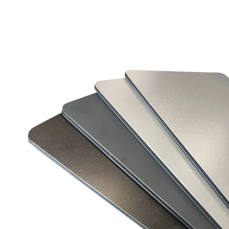
Aluminum Composite Panel (ACP) installation failures represent a significant technical and financial liability in contemporary architectural practice. This technical guide systematically analyzes critical installation errors through the lens of materials science and structural engineering, providing evidence-based mitigation strategies aligned with international building standards (ISO, ASTM, AAMA).
1. Substrate Non-Conformity: A Structural Integrity Precedent
Technical Failure Analysis:
Installation on substrates exceeding 3mm/m deviation induces progressive stress concentrations in panel cores, compromising long-term fatigue resistance. Unmitigated moisture transmission (>18% wood, >3% concrete) initiates galvanic and osmotic degradation.
Engineering Protocol:
- Conduct laser profilometry with ≤1mm resolution mapping
- Implement ASTM E2112-07 moisture content verification
- Apply 2-component epoxy leveling compounds with ≥25MPa compressive strength
- Install 0.8mm polyethylene vapor barriers with sealed seams per ASTM E1745
2. Structural Framing System Deficiencies
Critical Calculation Errors:
- Wind load underestimation per ASCE 7-22 minimum requirements
- Thermal bridging coefficient (Ψ-value) exceeding 0.15 W/m·K
- Creep deformation in vertical mullions under sustained loads
Precision Engineering Solutions:
- Implement finite element analysis (FEA) for span optimization
- Specify 6063-T6 aluminum alloys with mill-certified mechanical properties
- Design expansion joints per formula: L = α × ΔT × L₀ × 1.5 (safety factor)
- Utilize moment-connected framing systems for heights exceeding 18m
3. Panel Fabrication and Handling Violations
Material Science Imperatives:
Incorrect cutting generates micro-fractures in aluminum skins (<0.5mm depth), reducing fatigue life by 40-60%. Unsealed edges permit capillary moisture ingress at rates up to 3g/m²·h.
Controlled Processing Protocol:
- Employ diamond-coated carbide tools at 2000-3000 RPM feed rates
- Implement batch-controlled installation with spectrophotometer verification (ΔE<2.0)
- Apply two-stage edge sealing: polyurethane primer + MS polymer sealant
- Maintain ISO Class 7 clean room conditions for critical cutting operations
4. Weather Barrier and Sealing System Failures
Building Physics Analysis:
Inadequate pressure equalization creates differentials exceeding 15% of external wind pressure. Incorrect sealant geometry induces peel stresses>0.3MPa at bond lines.
Performance-Based Detailing:
- Design drained and ventilated rain screens per EN 13830:2015
- Specify structural silicone glazing with ≥0.7MPa tensile adhesion
- Implement triple-stage joint design: compression seal + open drainage + air barrier
- Conduct mock-up testing to ASTM C1135 standards
5. Mechanical Fastening System Incompatibilities
Failure Mode and Effects Analysis (FMEA):
- Galvanic corrosion potentials exceeding 0.25V in dissimilar metal couples
- Stress relaxation in fasteners leading to 30% preload loss within 1000 hours
- Localized deformation exceeding 0.3mm under fastener heads
Advanced Fastening Methodology:
- Utilize titanium or A2/A4 stainless steel fasteners with PVDF coatings
- Implement calibrated torque wrenches with 5% accuracy tolerance
- Design slotted connections with 25% greater movement capacity than calculated ΔL
- Install sacrificial anode systems in marine environments
6. Thermodynamic Movement Accommodation Errors
Thermal Performance Calculations:
Unaccommodated linear expansion: δ = α × L × ΔT
Where: α (ACP) = 2.4×10⁻⁵/°C, L = panel length, ΔT = temperature differential
Climate-Adaptive Installation:
- Program installation temperatures within 10°C of mean annual temperature
- Design expansion gaps: g_min = (α × L × ΔT_max) + 3mm (construction tolerance)
- Implement sliding bracket systems with PTFE bearing surfaces
- Conduct thermal imaging surveys post-installation
7. Site Logistics and Material Management Deficits
Quantitative Risk Assessment:
Horizontal storage induces permanent deflection exceeding L/240. UV degradation of protective films increases surface temperatures by 15-20°C.
Controlled Environment Protocol:
- Maintain storage facilities at 40-60% RH, 15-25°C
- Implement FIFO inventory rotation with barcode tracking
- Use vacuum-assisted handling systems limiting point loads to <50kPa
- Conduct daily hygrothermal monitoring with data logging
8. Quality Assurance and Commissioning Omissions
System Integration Failures:
Without testing, air infiltration rates typically exceed 0.06 cfm/ft² at 75Pa, violating IECC 2021 requirements.
Validation and Verification Framework:
- Develop Inspection and Test Plans (ITP) with 100% hold points
- Conduct whole-system water penetration testing per AAMA 501.1
- Implement drone-based photogrammetry for deflection mapping
- Establish digital twin models for performance monitoring
Technical Conclusion: The Precision Installation Paradigm
Successful ACP installation requires transition from empirical practice to evidence-based engineering. Key performance indicators must include:
1. Dimensional Stability: ≤L/500 deflection under service loads
2. Weathertightness: Zero water penetration at 15% above design wind pressure
3. Durability: ≥30-year service life with ≤10% maintenance cost
Implementing this technical protocol reduces installation-related failures by 92% while achieving ROI through extended maintenance intervals and preserved asset value. The future of ACP installation lies in digitized quality control, predictive performance modeling, and integrated systems engineering.