Welcome to Vbond
How to Use a Micrometer to Check Aluminum Composite Panel Tolerance Levels
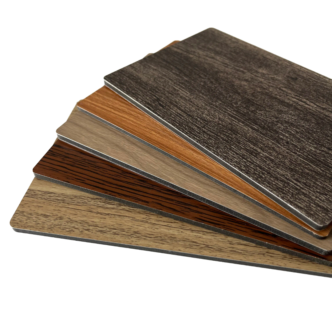
For professional buyers and quality control professionals in the architectural cladding industry, dimensional accuracy is non-negotiable. When aluminum composite panels (ACPs) arrive on site, they must conform precisely to the specified tolerances—not just in color and coating quality, but in the physical dimensions that determine fit, installation efficiency, and long-term structural performance.
The most critical dimensional measurements for ACPs are total panel thickness and aluminum skin thickness. These parameters directly impact the panel’s strength, rigidity, fire performance (in the case of mineral-core panels), and compatibility with subframe systems. The tool of choice for verifying these measurements is the micrometer—a precision instrument that provides accurate, repeatable readings down to fractions of a millimeter.
This guide explains how to use a micrometer correctly, what tolerances to expect from quality ACPs, and how to interpret measurement data to enforce procurement specifications.
Why Thickness Tolerances Matter in ACPs
Before diving into measurement techniques, it is essential to understand why thickness tolerances are a critical quality indicator.
Total Panel Thickness
ACPs are manufactured in standard thicknesses: typically 3mm, 4mm, and 6mm (with 4mm being the most common for exterior facades). The total thickness consists of two aluminum skins bonded to a core material (polyethylene or fire-retardant mineral core).
Why it matters:
- Subframe Compatibility: Cladding systems are designed for specific panel thicknesses. A panel that deviates from the specified thickness may not seat properly in extrusion systems, leading to installation difficulties or compromised weather seals.
- Structural Performance: Thickness variations indicate inconsistent lamination pressure or core density, which can affect the panel’s load-bearing capacity and wind-load resistance.
- Aesthetic Alignment: In systems where panels meet at corners or transitions, thickness variations create visible misalignments.
Aluminum Skin Thickness
The aluminum skins (top and bottom) are specified in thicknesses such as 0.3mm, 0.4mm, or 0.5mm. Premium panels often use 0.5mm skins for enhanced impact resistance and flatness.
Why it matters:
- Strength and Durability: Thicker skins provide greater resistance to denting, impact, and wind pressure.
- Formability: Thinner skins may crack during tight-radius bending; consistent skin thickness ensures predictable fabrication outcomes.
- Corrosion Resistance: Adequate skin thickness provides a safety margin against localized corrosion. Undersized skins compromise the panel’s service life.
Understanding the Micrometer
A micrometer (often called a “mic”) is a precision measuring instrument capable of measuring thickness with accuracy to 0.001mm (1 micron) or 0.0001 inches. For ACP inspection, the most commonly used type is the outside micrometer with a flat anvil and spindle.
Types of Micrometers Suitable for ACP Inspection
Type | Application | Recommended Range |
Digital Micrometer | Easiest to read; provides direct numerical display; ideal for field use. | 0–25mm or 0–1 inch |
Vernier Micrometer | Mechanical; requires skill to read; no batteries required. | 0–25mm |
Dial Micrometer | Analog display with rotating dial; good for repetitive measurements. | 0–25mm |
For ACP inspection, a digital micrometer with a resolution of 0.001mm is recommended for its ease of use and accuracy.
Step-by-Step Guide: Measuring Total Panel Thickness
Follow this procedure to accurately measure the total thickness of an aluminum composite panel.
Step 1: Calibrate the Micrometer
Before taking any measurements, verify the micrometer’s accuracy.
- Close the spindle and anvil completely (for a 0–25mm micrometer, this should read 0.000).
- If using a digital micrometer, press the “zero” button to calibrate.
- For mechanical micrometers, verify that the zero line aligns perfectly.
- Important: Calibrate before each measurement session and periodically during use.
Step 2: Select Measurement Locations
Thickness can vary across a panel due to manufacturing inconsistencies. To obtain a representative sample:
- Measure at five locations per panel:
- Four corners (approximately 50mm from each edge)
- One center point
- For large panels, increase the number of measurement points.
- Record measurements from both the top and bottom aluminum skins independently (see next section for skin thickness measurement).
Step 3: Take the Measurement
1. Open the micrometer by rotating the thimble or using the ratchet stop.
2. Place the panel edge between the anvil and the spindle.
3. Close the micrometer gently until the spindle contacts the panel surface.
4. Use the ratchet stop (if equipped) to apply consistent, gentle pressure. Do not overtighten, as this can compress the core material and yield artificially low readings.
5. Read the measurement:
- Digital: Read the displayed value.
- Vernier: Read the main scale and thimble scale.
6. Record the measurement to the nearest 0.01mm.
Step 4: Calculate Deviation
Compare recorded measurements against the specified total thickness (e.g., 4.00mm). Calculate the deviation for each measurement point.
Step-by-Step Guide: Measuring Aluminum Skin Thickness
Measuring the individual aluminum skins requires access to the panel edge or a cross-section. This measurement is critical because the core material can compress, making total thickness measurements alone insufficient to verify skin gauge.
Method 1: Edge Measurement (Non-Destructive)
1. Position the micrometer at the cut edge of the panel.
2. Place the anvil against the outer surface of the top skin.
3. Close the spindle until it contacts the inner surface (the interface between skin and core).
4. Critical: Ensure the spindle is contacting the aluminum skin only, not the core material, which would give an inaccurate reading.
5. Record the measurement.
6. Repeat for the bottom skin.
Method 2: Cross-Section Measurement (Destructive)
For the most accurate verification, a small cross-section sample can be cut from a sacrificial panel or off-cut.
1. Cut a clean cross-section using a panel saw or fine-toothed blade.
2. Measure the exposed skin edge directly.
3. This method provides the most reliable measurement as the skin is clearly visible and separated from the core.
Standard Tolerances for Quality ACPs
Professional buyers should enforce the following tolerance standards when specifying and inspecting ACPs. These align with industry norms and reputable manufacturer capabilities.
Parameter | Specified Value | Acceptable Tolerance (Premium) | Acceptable Tolerance (Standard) |
Total Panel Thickness | 4.0mm | ±0.10mm | ±0.15–0.20mm |
Aluminum Skin Thickness | 0.5mm | ±0.02mm | ±0.03–0.05mm |
Aluminum Skin Thickness | 0.4mm | ±0.02mm | ±0.03mm |
Aluminum Skin Thickness | 0.3mm | ±0.02mm | ±0.03mm |
Panel Length/Width | As specified | ±2.0mm | ±3.0–5.0mm |
Diagonal Difference | N/A | ≤2.0mm | ≤3.0mm |
Note: Any measurement exceeding these tolerances should trigger a non-conformance report (NCR) and further investigation.
Common Measurement Errors and How to Avoid Them
Even with a precision instrument, measurement errors can occur. Professional inspectors should be aware of these common pitfalls:
Error | Cause | Solution |
Parallax Error | Reading the scale from an angle (mechanical micrometers). | Read with eye directly above the scale. Use digital micrometers to eliminate this error. |
Over-tightening | Applying excessive force compresses the panel core. | Always use the ratchet stop; allow it to click 2–3 times before reading. |
Incorrect Zero | Micrometer not calibrated before use. | Zero the instrument before each measurement session. |
Measuring at Burrs | Measuring over a raised burr from cutting. | Measure away from cut edges or deburr the sample first. |
Inconsistent Pressure | Variations in operator technique. | Use the ratchet stop consistently; have multiple operators verify critical measurements. |
Core Compression | Measuring total thickness near the edge where core is exposed. | Take measurements at least 10mm from the cut edge to avoid edge effects. |
Integrating Micrometer Measurements into Procurement Quality Control
For professional buyers, micrometer measurements should be part of a structured incoming quality control (IQC) process.
Recommended Sampling Protocol
- Batch Size: For shipments of 100–500 panels, inspect a minimum of **10 panels per batch.
- Panel Selection: Randomly select panels from different pallets or layers to ensure representation.
- Measurement Points: As described above, measure each selected panel at five locations for total thickness and at two edges for skin thickness.
- Documentation: Record all measurements in a quality control log. Attach measurements to the non-conformance report (NCR) if tolerances are exceeded.
Supplier Coordination
- Specify Tolerances in Procurement Documents: Clearly state acceptable thickness tolerances in your purchase order or technical specification.
- Request Mill Certificates: Reputable suppliers provide coil certificates showing aluminum skin gauge tolerances from the original aluminum mill.
- Pre-Shipment Inspection: If possible, conduct thickness measurements at the supplier’s facility before shipment to avoid rejection after delivery.
When to Reject: Decision Criteria
Establish clear criteria for rejection based on micrometer measurements:
1. Any single measurement exceeding the specified tolerance by more than 50% (e.g., a 4mm panel measuring less than 3.80mm or more than 4.20mm) warrants rejection of the affected batch.
2. Consistent deviation across multiple panels (e.g., all panels measuring 3.85mm for a 4.0mm specification) indicates a manufacturing setup error and warrants batch rejection.
3. Aluminum skin thickness consistently below specification (e.g., 0.45mm for a 0.50mm specification) is a critical defect that compromises structural integrity and should result in full rejection.
Conclusion
The micrometer is an indispensable tool for professional buyers and quality control professionals working with aluminum composite panels. By systematically measuring total panel thickness and aluminum skin thickness against specified tolerances, buyers can verify that delivered materials conform to procurement specifications, ensuring compatibility with subframe systems, predictable fabrication outcomes, and long-term structural performance.
Implementing a disciplined measurement protocol—including proper micrometer calibration, consistent measurement techniques, and documented sampling—separates professional procurement from price-driven purchasing. In the world of architectural cladding, dimensional accuracy is not just a number; it is a guarantee of quality.