Welcome to Vbond
Why Your CNC Router Causes Delamination in ACP: Spindle Speed and Feed Rate Optimization
You have invested in a premium Aluminum Composite Panel (ACP). The sheets arrived flawless. But the moment your CNC router touches the material, the edges fray, the top aluminum skin peels away, or the core melts into a sticky mess. Your scrap pile grows. Your profit margin shrinks.
The most common culprit is not the machine quality. It is the relationship between spindle speed (RPM) and feed rate (IPM or mm/min). When these two variables are not perfectly balanced, the tool does not cut the material—it tears, burns, or delaminates it.
This guide provides the technical specifications for spindle speed and feed rate optimization to eliminate delamination and achieve clean, precise cuts on every ACP panel.
1. The Delamination Mechanism: What Happens When Settings Are Wrong
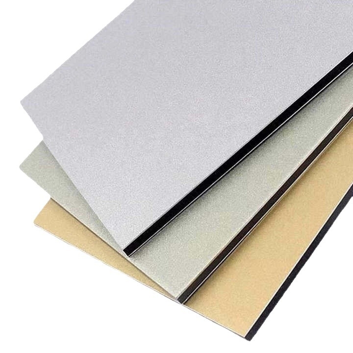
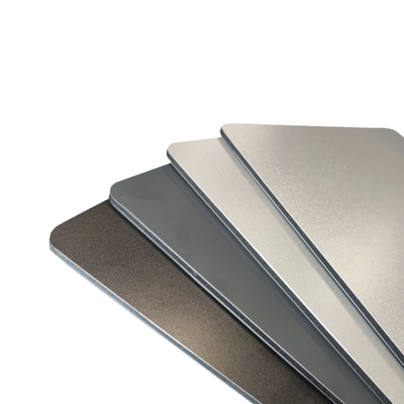
Aluminum Composite Panel consists of two thin aluminum skins bonded to a polyethylene or mineral-filled core. Cutting through this sandwich requires a tool that shears the aluminum cleanly and evacuates the core material without melting it.
The Consequences of Imbalance
Condition | Result | Failure Mode |
RPM too high / Feed too slow | RPM too high / Feed too slow | Melts polyethylene core; gumming on tool |
RPM too low / Feed too fast | The tool teeth bite too aggressively | Tears in the aluminum skin; delamination at the entry/exit |
Incorrect tool direction | Up-cut lifts the top skin | Fraying; surface delamination |
Incorrect tool geometry | No shearing action | Burrs; rough edges |
When the tool spins faster than the forward movement can clear chips, the bit rubs against the material instead of cutting. The friction generates heat that melts the core. Molten polyethylene adheres to the tool, creating a buildup that further increases friction—a destructive feedback loop that ruins the panel and dulls the bit.
Conversely, when the forward speed exceeds the tool's ability to remove material, the cutting edges overload, tearing the aluminum rather than shearing it. The result is delamination at the cut line, where the aluminum skin separates from the core.
2. Tool Selection: The Foundation for Clean Cuts
Before setting speeds and feeds, you must select the correct tool geometry for ACP.
Compression Spirals: The Anti-Delamination Solution
Compression router bits are specifically designed to prevent delamination in laminated materials like ACP. Unlike up-cut bits that pull the top surface upward or down-cut bits that push debris downward, compression bits combine both geometries.
How Compression Bits Work:
The lower portion of the compression bit has up-cut geometry, pulling chips upward from the bottom of the material. The upper portion has down-cut geometry, pushing chips downward from the top surface. The forces meet at the centerline of the material, "compressing" the layers together rather than pulling them apart.
Benefits for ACP Machining:
Feature | Benefit |
No delamination on top or bottom | Clean edges on both aluminum skins |
Full-depth cutting in one pass | Higher productivity; consistent edge quality |
Reduced fixture requirements | Compression forces hold material down naturally |
V-Groove Bits for Folding
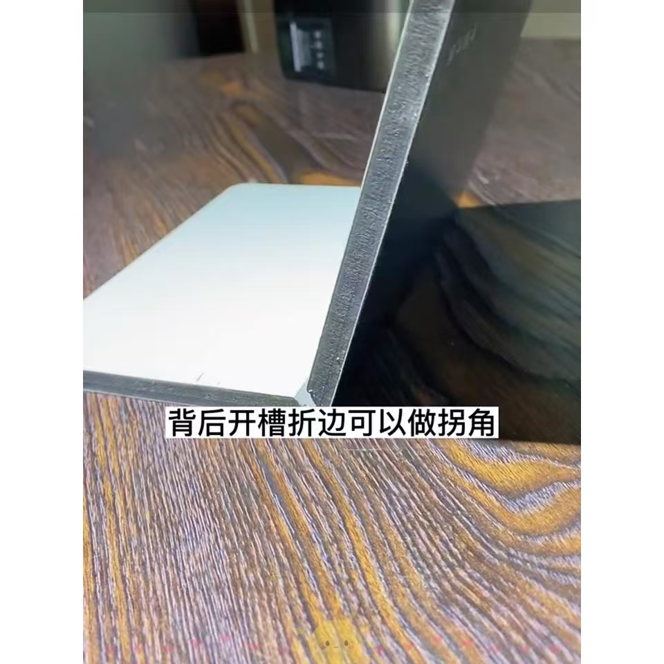
For applications requiring folded edges (cassette fabrication), use a 90-degree V-groove bit with a flat tip. A bit that comes to a full point does not leave enough room for the material to bend properly, causing stress cracking at the fold line.
Critical Requirement: The V-groove should cut through the top aluminum skin and the core, stopping as close as possible to the bottom aluminum skin without cutting through it . This leaves a thin, flexible hinge that folds cleanly without breaking.
3. Spindle Speed and Feed Rate: The Optimization Formula
Cutting Through ACP (Full Thickness)
For straight cutting through 3mm ACP, documented successful parameters are:
Parameter | Setting |
Tool | 1/4″ single O-flute upcut bit |
Feed rate | 200 inches per minute (IPM) |
Spindle speed | 22,000 RPM |
Cut direction | Climb cutting |
Passes | 1 pass through full thickness |
The single O-flute design provides large chip clearance, preventing core material from packing into the flutes. Climb cutting (where the tool rotates in the same direction as the feed movement) produces a cleaner edge on aluminum compared to conventional cutting.
General Recommendations for ACP Routing
Industry guidelines for ACP routing specify:
Panel Thickness | Tool Diameter | Feed Rate | Spindle Speed |
< 4 mm | 4 mm bit | 80 mm/sec (4,800 mm/min) | 25,000 RPM |
> 4 mm | 4 mm bit (multipass) | 80 mm/sec | 25,000 RPM |
< 4 mm (HF spindle) | 6 mm bit | 120 mm/sec | 35,000 RPM |
< 6 mm (HF spindle) | 6 mm bit | 100 mm/sec | 35,000 RPM |
The "Goldilocks" Principle
The ideal combination creates chips that are:
- Not too fine (indicates rubbing, not cutting—increase feed or reduce RPM)
- Not too large and ragged (indicates overload—reduce feed or increase RPM)
- Warm to the touch, not hot (heat indicates friction, not shearing)
When parameters are correct, the aluminum chips should form small, consistent curls. The core material should be evacuated as fine powder or small granules, not melted strings.
4. V-Grooving Parameters for Folded Panels
V-grooving requires different parameters than through-cutting because the tool only removes the top aluminum skin and core, leaving the bottom skin intact.
Parameter | Setting |
Tool | 90-degree V-groove bit with flat tip |
Feed rate | 150 inches per minute (IPM) |
Spindle speed | 14,000 RPM |
Passes | 1 pass |
The lower spindle speed (14,000 RPM vs. 22,000 RPM for through-cutting) reduces heat buildup, preventing core melting. The flat tip on the V-groove bit leaves a small flat at the bottom of the groove, providing space for the material to bend without stress cracking .
Depth Control for V-Grooving:
The goal is to cut through the top aluminum skin and the core, stopping as close as possible to the bottom aluminum skin without cutting through it. This requires precise Z-axis control. If you cut through the bottom skin, the hinge is destroyed. If you leave too much core material, the panel will resist bending and may crack.
5. Tool Direction and Cutting Strategy
Climb vs. Conventional Cutting
For ACP, climb cutting (also called climb milling) produces superior edge quality on the aluminum skins. In climb cutting, the tool rotates in the same direction as the feed movement. The cutting edge engages the material at maximum thickness and exits at zero thickness, shearing the aluminum cleanly.
Conventional cutting (tool rotates opposite to feed direction) can cause the cutting edge to rub and push through the material, creating burrs and rough edges on aluminum.
Multi-Pass vs. Single-Pass
The quality of an edge is best if the material is routed in one pass. However, for thicker panels (exceeding 6mm), multipass may be necessary to prevent tool overload and core melting.
Important Rule for Multi-Pass Cutting: The first pass must cut through the bottom aluminum skin. If the first pass stops in the core material, the foam may melt from the heat of the subsequent pass, creating a rough, melted edge.
6. Chip Evacuation and Heat Management
Heat is the enemy of ACP routing. Polyethylene core material begins to soften at approximately 120°C. Once it melts, it adheres to the tool, creating a buildup that further increases friction and heat.
Strategies for Heat Reduction
Strategy | Implementation |
Use compression bits | Forces chips away from the cut zone |
Maintain proper feed rate | Prevents rubbing; ensures chips carry heat away |
Use climb cutting | Reduces friction at tool entry |
Vacuum chip removal | Removes hot chips before they can melt onto the tool |
Mist lubrication (for heavy cuts) | Reduces friction; extends tool life |
Warning Signs of Overheating
- Discoloration (browning) of core material at the cut edge
- Melted plastic strings attached to the cut edge
- Residue buildup on tool flutes
- Smoke or burning smell during cutting
- Dull, melted appearance of core rather than clean cut
7. Machine Capability Considerations
Not all CNC routers can maintain programmed feed rates on small features. Machine acceleration/deceleration (acc/dec) limitations can prevent the tool from reaching optimal cutting speeds on tight contours.
The Acc/Dec Challenge:
On small-diameter features (pockets, tight corners, small holes), the machine axes may not have enough travel distance to accelerate to the programmed feed rate before decelerating for the next direction change. The result is that the tool spends most of its time at reduced feed rates, increasing heat buildup and reducing edge quality.
Solutions:
- Use adaptive toolpaths that maintain constant tool engagement
- Increase feature size where design permits
- Consider a machine with higher acc/dec capability for high-volume production of small parts
- Reduce programmed feed rate on small features to match the machine's actual capability
8. Parameter Summary Table
Operation | Tool Type | Feed Rate | Spindle Speed | Notes |
Through-cut (3mm ACP) | 1/4″ single O-flute upcut | 200 IPM | 22,000 RPM | Climb cut; 1 pass |
Through-cut (<4mm) | 4 mm bit | 80 mm/sec | 25,000 RPM | Counterclockwise rotation |
Through-cut (<4mm, HF) | 6 mm bit | 120 mm/sec | 35,000 RPM | Counterclockwise rotation |
Through-cut (<6mm, HF) | 6 mm bit | 100 mm/sec | 35,000 RPM | Counterclockwise rotation |
V-Grooving | 90° flat-tip V-bit | 150 IPM | 14,000 RPM | 1 pass; stop at the bottom skin |
Drilling holes | 2-flute carbide drill | 100 IPM (plunge) | 4,000 RPM | - |
9. Conclusion
CNC router delamination in aluminum composite panels is not a mystery. It is a predictable result of incorrect spindle speed and feed rate relationships. When RPM is too high relative to the feed rate, heat melts the core. When the feed rate is too high relative to RPM, the tool tears the aluminum skins.
The solution is precision. Use compression bits that pull the material together rather than apart. Match your speeds and feeds to documented parameters. Verify chip formation and edge quality on test cuts before production runs. And respect the thermal limits of the polyethylene core—heat is the enemy, and proper chip evacuation is your primary defense.
When your parameters are optimized, ACP cuts cleanly, folds precisely, and installs flawlessly. Your scrap pile shrinks. Your productivity rises. And your reputation for quality grows.