Welcome to Vbond
The Laser Scanner Method: Pre-Installation Keel Curvature Detection for Alucobond
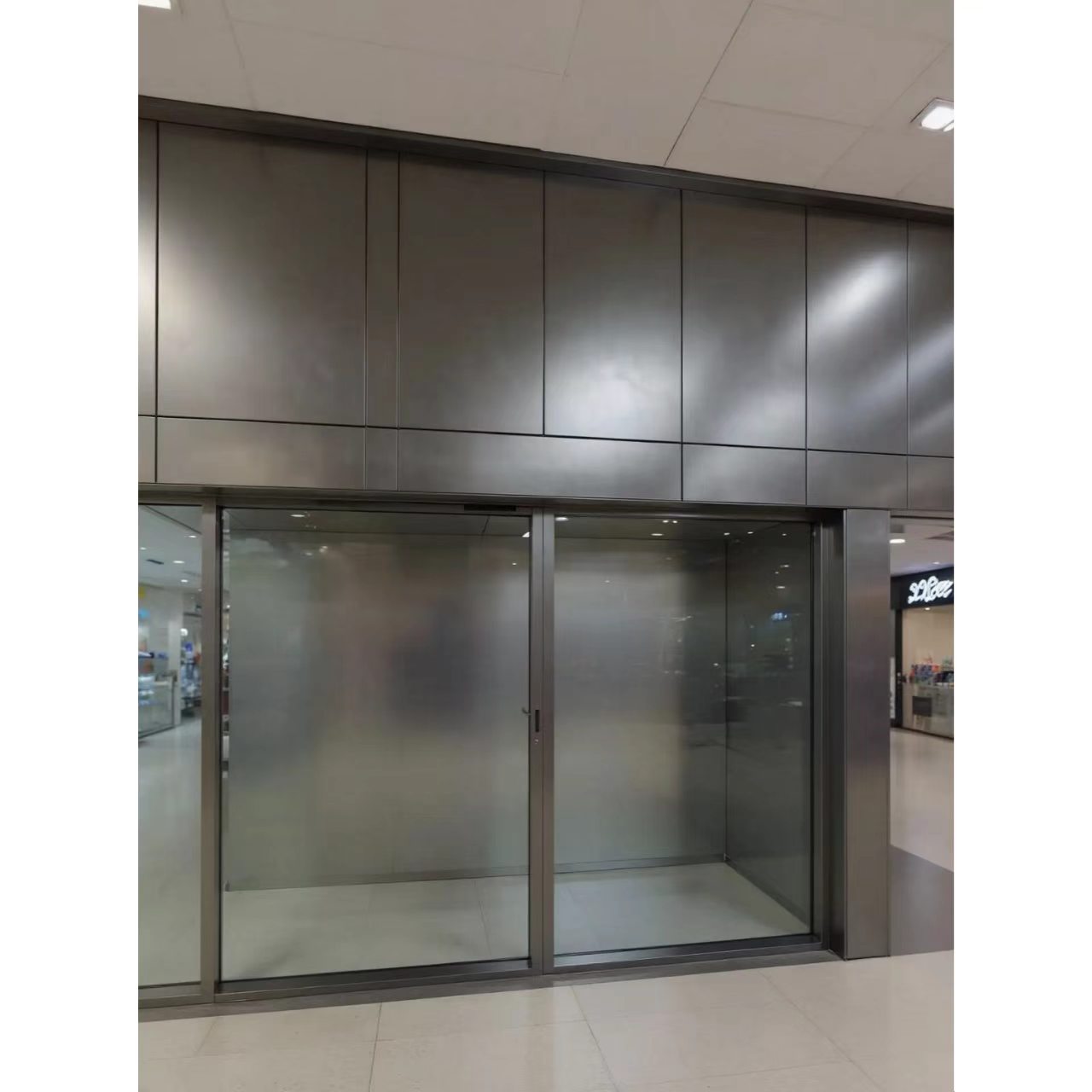
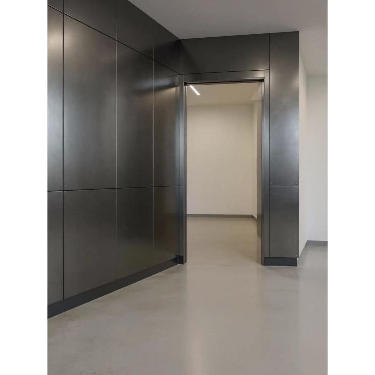
You stand in front of the finished facade. The panels look flawless. The client approves.
Three months later, the sun hits the building at a certain angle. You see them. Waves. Ripples. Distortion across the once-perfect surface.
The panels are flat. The material is premium. The installation was meticulous. The problem was invisible at the time—a subframe that looked straight but wasn't.
This guide introduces the laser scanner method for pre-installation keel curvature detection. You will learn how laser scanning works. You will understand why it is superior to traditional methods. And you will know exactly how to use it to prevent wavy Alucobond facades.
Part 1: The Problem with Traditional Inspection Methods
Traditional subframe inspection relies on manual tools: a 2-meter straightedge, a spirit level, and a tape measure. These tools have significant limitations.
The limitations of traditional methods:
Method | Limitation | Consequence |
2m straightedge | Only detects deviations over 2m spans | Misses long-span curvature |
Spirit level | Only checks plumb and level | Misses diagonal and complex curvature |
Tape measure | Only checks individual dimensions | Misses cumulative deviations |
Visual inspection | Subjective | Misses subtle curvature |
String line | Only checks straightness in one plane | Misses three-dimensional curvature |
The problem:
A subframe can look straight to the naked eye. It can pass a 2-meter straightedge test. But it can still have significant curvature over longer spans. A 6-meter rail can bow 5- 8 mm in the middle while appearing straight when checked with a 2-meter straightedge.
The consequence for Alucobond panels:
An Alucobond 4x8 sheet (approximately 1220mm x 2440mm) spans across the subframe. If the subframe has a curvature of just 3-4mm over the panel width, the panel will follow that curvature. The facade will show visible waves.
Traditional methods cannot detect this curvature. Laser scanning can.
Part 2: How Laser Scanning Works
Laser scanning is a 3D measurement technology that uses a laser beam to capture the exact geometry of a surface. The scanner projects a laser beam onto the target surface and measures the time it takes for the beam to return. This creates a "point cloud"—a set of millions of 3D coordinates that precisely map the surface.
The process:
Phase | Action | Output |
1. Set up scanner | Position the scanner at the site | Scanner ready |
2. Scan subframe | Capture data from multiple positions | Point cloud dataset |
3. Process data | Software analyzes the point cloud | 3D model of subframe |
4. Detect deviations | Identify areas outside tolerance | Curvature report |
5. Correct issues | Shim or adjust subframe | Flat subframe ready for installation |
What laser scanning reveals:
- Curvature over long spans (4m, 6m, or more)
- Twist in rails
- Misalignment of brackets
- Cumulative deviations
- 3D geometry of the entire subframe
The precision:
Laser scanners can detect deviations as small as 1- 2 mm over a 10m span. This is far more precise than any manual method.
Part 3: Why Laser Scanning Matters for Alucobond 4x8 Sheets
An Alucobond 4x8 sheet is a large panel. 1220mm x 2440mm. Nearly 3 square meters of surface area. It spans across multiple rails and brackets. The subframe must be flat across the entire panel footprint.
The laser scanner advantage:
Factor | Traditional Inspection | Laser Scanning |
Detection of long-span curvature | No | Yes |
Detection of twist | No | Yes |
3D measurement | No | Yes |
Precision | ±2-3mm | ±1-2mm |
Documentation | Manual records | Digital point cloud |
Time for 100 sqm | 1-2 days | 2-4 hours |
What laser scanning catches:
- Rail bowing: A rail can bow 3- 5 mm in the middle without being detected by a straightedge
- Rail twist: A rail can be twisted along its length
- Bracket misalignment: Brackets can be out of alignment by 2- 3 mm
- Cumulative deviations: Small deviations that add up across a large facade
All of these would cause visible waves in an Alucobond 4x8 sheet. All of these can be detected and corrected before installation.
Part 4: The Laser Scanning Workflow
Step 1: Site preparation
Before scanning, ensure the subframe is complete. All rails and brackets should be installed. The site should be clear of debris and obstructions that could block the scanner's line of sight.
Step 2: Scanner placement
Position the scanner at strategic locations on site. The scanner should have a clear line of sight to the entire subframe area. Multiple scans may be needed to cover large areas.
Step 3: Data capture
The scanner projects a laser beam onto the subframe. It captures millions of points, creating a "point cloud" that precisely maps the geometry.
Step 4: Data processing
Software processes the point cloud data. It creates a 3D model of the subframe. It identifies any deviations from the design geometry.
Step 5: Deviation analysis
The software compares the actual subframe geometry to the design specifications. It identifies areas that exceed tolerances.
Step 6: Correction
Mark the out-of-tolerance areas. Shim, adjust, or realign the subframe. Re-scan to verify correction.
Step 7: Documentation
Create a report documenting the scan results. Include deviation maps, correction recommendations, and final verification.
Part 5: Interpreting Laser Scanner Results
The tolerance standard:
Parameter | Tolerance |
Surface flatness | ≤2mm over 2m |
Long-span curvature | ≤3mm over 4m |
Bracket alignment | ±1mm |
Rail twist | ≤2mm over 3m |
What the data shows:
Deviation | Interpretation | Action |
≤2mm over 2m | Within tolerance | No action needed |
2-4mm over 2m | Minor deviation | Shim or adjust |
>4mm over 2m | Major deviation | Rebuild or realign |
>5mm over 4m | Long-span curvature | Adjust rail, add support |
The warning signs:
- Gradual curvature: The subframe shows a gentle curve over a long span. This indicates that the rails are bowing.
- Twist: The subframe shows a twisting deviation. This indicates that the rails are not aligned.
- Bracket deviations: Individual brackets are out of alignment. This indicates installation errors.
For an Alucobond 4x8 sheet:
A 4x8 sheet spans 1220mm across multiple rails. If the subframe has a curvature of just 3- 4 mm over this span, the panel will show visible waves. The laser scanner will catch this curvature before installation.
Part 6: Cost-Benefit Analysis
Factor | Traditional Inspection | Laser Scanning |
Equipment cost | Low ($200-500) | High ($30,000-100,000) |
Labor time (100 sqm) | | 1-2 days | 2-4 hours |
Data accuracy | Moderate | High |
Detection of long-span curvature | No | Yes |
Detection of twist | Limited | Yes |
Risk of rework after installation | High | Low |
Total project cost impact | Higher (rework) | Lower (rework avoided) |
The economic case:
A single Alucobond 4x8 sheet replacement costs $600-900 installed. If poor subframe flatness causes visible waves across 100 panels, the rework cost is $60,000-90,000—far more than the cost of laser scanning.
Laser scanning costs approximately $2,000-5,000 for a 1,000 sqm project. It takes 2-4 hours. It prevents months of rework.
The cost-benefit calculation is simple: scanning saves money.
What to Ask Your Supplier
When you purchase an Alucobond 4x8 sheet for your project, ask these questions:
1. Do you provide laser scanning services for subframe verification? A professional supplier will recommend or provide scanning services.
2. What are your subframe flatness requirements? The answer should include long-span curvature tolerances.
3. Do you have experience with laser scanner verification? Experienced suppliers can guide you through the process.
4. What scanning software do you use? The answer should be a recognized industry package.
Common Mistakes to Avoid
Mistake 1: Relying only on the 2-meter straightedge
The straightedge cannot detect long-span curvature. A rail can bow 5mm over 6m and still pass the 2m test.
Fix: Use laser scanning for long-span curvature detection.
Mistake 2: Scanning only one orientation
A subframe can be flat horizontally but wavy diagonally. The panel will show the diagonal waves.
Fix: Scan in multiple orientations. Use 3D analysis software.
Mistake 3: Not documenting the scans
Without documentation, you cannot prove the subframe was flat. If the panel waves later, the liability defaults to you.
Fix: Document all scan results. Retain data for project records.
Mistake 4: Assuming the subframe is flat because it "looks" flat
Subframes can look flat but have significant curvature. The human eye cannot detect subtle deviations.
Fix: Measure, do not assume. Use laser scanning.
The Bottom Line
The laser scanner method changes everything. It transforms subframe inspection from a subjective, error-prone manual process into a precise, data-driven science. It detects deviations as small as 1-2mm. It catches curvature that the eye misses. It provides digital documentation that protects you.
Traditional methods are obsolete. They cannot detect long-span curvature. They cannot detect twist. They cannot provide a digital record of the subframe condition.
For an Alucobond 4x8 sheet, the stakes are particularly high. The panel spans a large area. The subframe must be flat across the entire footprint. Laser scanning verifies flatness before installation, not after—when there is still time to correct.
A 4x8 panel—nearly 3 square meters of surface—will follow every contour of the subframe behind it. If that subframe has a gentle curve of just 3- 4 mm, the panel will wave. Laser scanning catches that curve. Laser scanning prevents that wave. Laser scanning saves that facade.
When you walk that site twelve months from now, standing in front of a flat, flawless Alucobond facade with no waves in sight, you will know—not hope, not guess, but know—that the subframe is flat. Because you scanned it. Because you caught the curvature before installation. Because you refused to let an invisible deviation destroy a premium facade.
The panel is only as flat as the subframe behind it. Scan that subframe. Your facade depends on it.