Welcome to Vbond
Wind Load Deflection: Calculating the Right Support Density for Alucobond
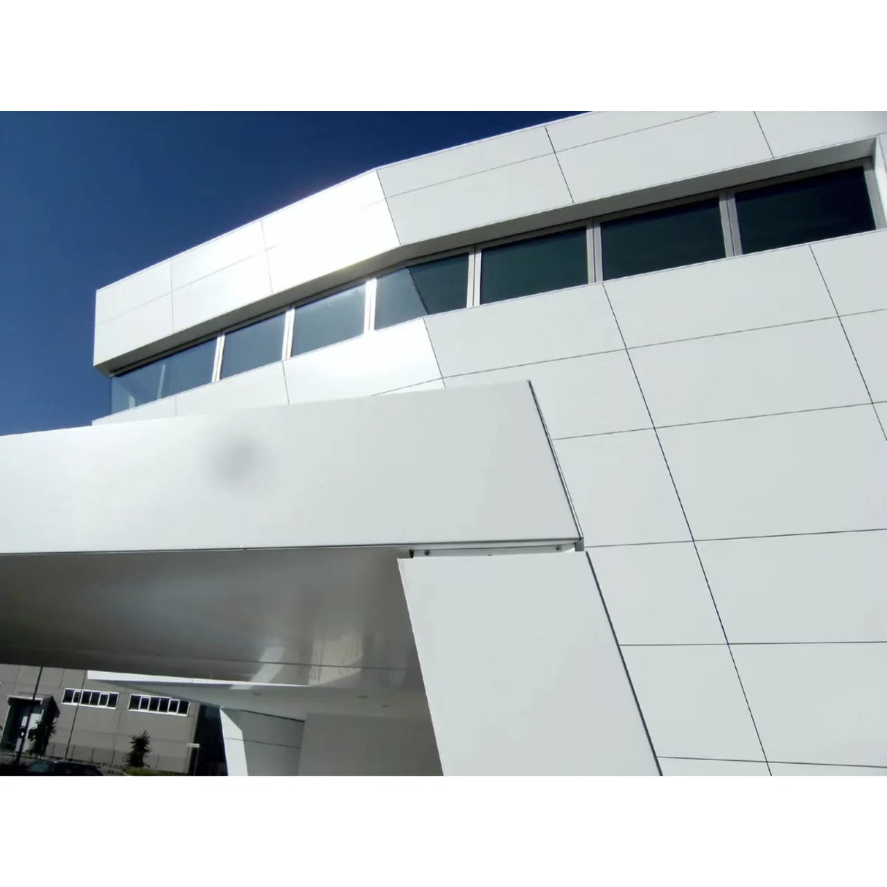
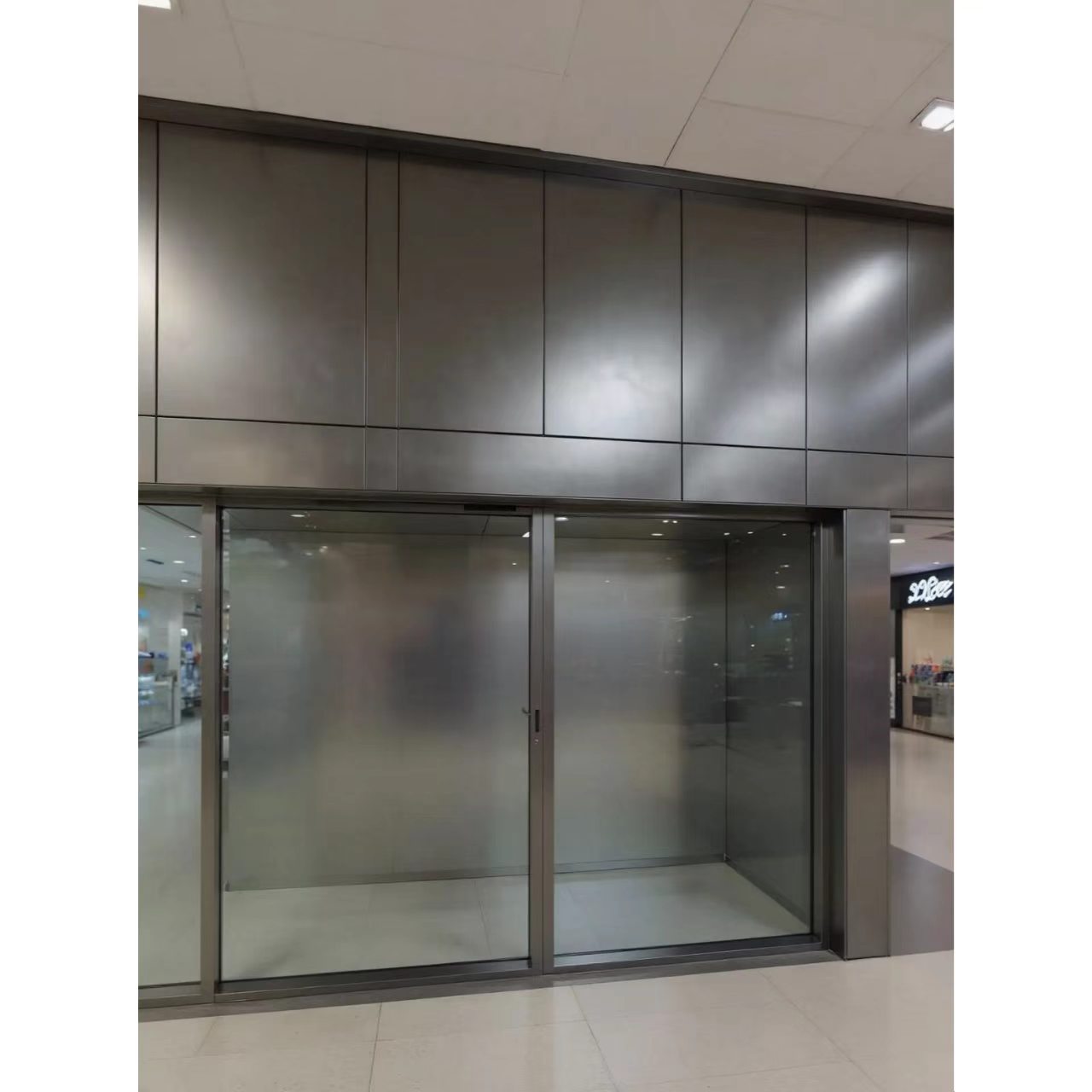
You specify a beautiful Alucobond facade. The panels are large. The design is clean. The renderings look stunning.
Then the wind hits the building. You see them. Waves. Ripples. Distortion across the panel surface. The sleek facade now looks uneven.
The problem is not the material. The problem is the support density. The skeleton is too sparse. The panel is deflecting under load.
This guide explains how to calculate the right support density for Alucobond panels under wind load. You will learn the physics behind deflection. You will understand the key formulas. And you will know exactly how to space your supports for a flat, distortion-free facade.
Part 1: Why Wind Load Deflection Matters
Wind does not push evenly on a building. It pushes harder on some areas than others. Corner zones experience suction forces two to three times higher than the center of the wall. Parapet edges take the worst of it.
For a typical high-rise facade, design wind loads reach 2.0 to 5.0 kPa. Negative pressure (suction) often governs the design. It can be significantly higher than positive pressure on the same surface.
What deflection does to your facade:
- Visible waves and ripples across the panel surface
- Stress concentration at fastener points
- Fatigue of the adhesive bond between skin and core
- Premature blistering and delamination
- Client complaints and costly rework
The stakes are higher for a 6mm Alucobond panel. While thicker panels offer enhanced rigidity for large-scale exterior applications—particularly in areas with extremely high wind loads—they also tend to be used in precisely the conditions where wind loads are most severe. A 6mm panel used in a high-wind zone with insufficient support will deflect just as visibly as a thinner panel.
Part 2: The Physics of Panel Deflection
An Alucobond panel is a sandwich structure. Two aluminum skins bond to a core. When wind pressure hits the panel, it bends. That bending is called deflection.
The fundamental deflection formula for a rectangular panel:
y_max = (α × w × b⁴) / (E_ACM × T³_ACM)
Where:
y_max = maximum deflection at panel center
α = coefficient depending on panel aspect ratio and support conditions
w = uniform wind load (pressure)
b = smallest panel dimension (span between supports)
E_ACM = modulus of elasticity of the panel
T_ACM = effective panel thickness
The key takeaway:
Deflection is proportional to the fourth power of the span (b⁴). This is critical. Double the support spacing, and deflection increases by a factor of 16. Halve the spacing, and deflection decreases by a factor of 16.
Small changes in support spacing have massive effects on panel flatness. A spacing that works for a 4mm panel may cause unacceptable deflection for a 6mm Alucobond panel if used in a high-wind zone—because the loads are higher and the panels are larger.
Part 3: The Critical Numbers
Permissible design stress for Alucobond plus:
The permissible design stress is σ = 51 N/mm² with a safety factor of 1.75 taken into account.
Deflection limits from JGJ 255-2012:
When metal panels are subjected to wind loads, "the middle ribs should have sufficient stiffness, and their deflection should not exceed 1/300 of the rib span".
Rib Span | Maximum Allowed Deflection |
600 mm | 2.0 mm |
900 mm | 3.0 mm |
1200 mm | 4.0 mm |
Maximum support spacing from ALUCOBOND guidelines:
"The distance between stiffeners should not be more than 600mm". Stiffeners should be fixed to the back of the panel based on the size of each panel and wind load calculations of the project site.
Maximum design wind load:
The maximum allowable design wind load pressure for Alucobond panels installed using the rout-and-return method with aluminum extrusion frames is 25 psf (1.2 kPa), positive or negative.
Part 4: Support Density by Panel Thickness
Different panel thicknesses have different stiffness. The key metric is flexural rigidity (E·J) —a measure of how much the panel resists bending.
Alucobond plus flexural rigidity:
Panel Thickness | Flexural Rigidity (E·J) | Weight | Application |
3mm | 1,250 kNcm²/m | 4.5 kg/m² | Lightweight, low wind |
4mm | 2,400 kNcm²/m | 5.5 kg/m² | Standard facade |
6mm | Higher than 4mm | 7.3 kg/m² | High wind, large format |
A 6mm Alucobond panel weighs approximately 7.3 kg/m²—significantly more than a 4mm panel. It is typically used in large-scale exterior applications, particularly in areas with extremely high wind loads or for panels that are exceptionally large.
What this means for support density:
The 6mm panel has greater rigidity than thinner panels. This allows for slightly wider support spacing under the same wind load. However, because 6mm panels are typically used in higher-wind applications, the actual support spacing often ends up being similar to or even tighter than 4mm panels in standard conditions.
Part 5: The Support Density Calculation
Step 1: Determine the design wind load
Calculate the design wind load for your project based on:
- Building height and location
- Exposure category (open, suburban, urban)
- Wind speed per local building code
- Corner and edge zone multipliers
Step 2: Determine the maximum allowable deflection
For a 6mm Alucobond panel, the deflection limit is L/300 of the span. For a typical 600mm support spacing, the maximum deflection is 2.0 mm.
Step 3: Calculate the required support spacing
Using the deflection formula, work backward to find the maximum span that keeps deflection within the L/300 limit.
Simplified approach:
For a given wind load and panel thickness, the maximum support spacing can be determined from manufacturer load tables.
For 4mm panels on a timber frame:
Load (kN/m²) | Max. Support Width (Suction) | Max. Support Width (Pressure) |
0.50 | 783 mm | 943 mm |
0.80 | 669 mm | 806 mm |
1.00 | 621 mm | 748 mm |
1.20 | 584 mm | 704 mm |
1.60 | 551 mm | 640 mm |
2.00 | 493 mm | 594 mm |
Source: ALUCOBOND load table for 4mm panels on 2 supports.
What this tells us:
Even for 4mm panels, support spacing must be reduced as wind load increases. At 1.2 kPa, the maximum support width is approximately 584 mm. At 2.0 kPa, it drops to 493 mm.
For a 6mm Alucobond panel, the increased rigidity allows for slightly wider spacing, but the exact values depend on the specific panel type and support system.
Part 6: The Role of Mid-Ribs
Mid-ribs are stiffening members attached to the back of the panel. They divide the panel into smaller zones, reducing the unsupported span.
How mid-ribs help:
- A panel with mid-ribs has multiple support lines
- The effective span is reduced to the distance between mid-ribs
- Deflection is reduced dramatically
Mid-rib guidelines:
Stiffeners should be fixed to the back of the panel based on the size of each panel and wind load calculations for the project site. The distance between stiffeners should not be more than 600mm.
For 6mm panels in high-wind zones:
If wind loads exceed 1.2 kPa, mid-ribs are recommended even for 6mm panels. The increased rigidity of the 6mm panel helps, but it cannot compensate for excessive spans under extreme loads.
Part 7: The Design Flowchart
Start
│
▼
Determine design wind load (w) for your project
├─── Building height and location
├─── Exposure category
└─── Corner/edge zone multipliers
│
▼
Select panel thickness
├─── 6mm panel for high wind / large format
└─── 4mm panel for standard applications
│
▼
Determine deflection limit (L/300 per JGJ 255-2012)
│
▼
Calculate maximum support spacing
├─── Using manufacturer load tables
└─── Or using deflection formula
│
▼
Check against maximum 600mm spacing
│
├─── Spacing >600mm ───► Reduce to 600mm maximum
└─── Spacing ≤600mm ───► Proceed
│
▼
Add mid-ribs for large panels or high wind loads
│
├─── Mid-rib spacing ≤600mm
└─── Connect securely to edge ribs
│
▼
Verify deflection ≤ L/300
│
▼
DONE ───► Flat Alucobond facade with no deflection
Part 8: Common Mistakes to Avoid
Mistake 1: Ignoring wind load calculations
Wind load varies by building height, location, and exposure. A spacing that works on a low-rise building will fail on a high-rise.
Fix: Calculate the design wind load for your project. Adjust spacing accordingly.
Mistake 2: Exceeding the 600mm maximum
The ALUCOBOND guideline states that the distance between stiffeners should not be more than 600mm. This is the absolute maximum.
Fix: Never exceed 600mm spacing, regardless of panel thickness.
Mistake 3: Assuming thicker panels need no support
A 6mm Alucobond panel has greater rigidity than a 4mm panel. But it does not eliminate the need for proper support. In high-wind zones, even 6mm panels require mid-ribs and proper spacing.
Fix: Calculate support requirements based on wind load, not panel thickness alone.
Mistake 4: Ignoring corner and edge zones
Corner zones experience suction forces two to three times higher than the wall center. Spacing that works on the main wall will fail at the corners.
Fix: Reduce support spacing in corner and edge zones.
Mistake 5: Skipping mid-ribs for large panels
Large panels deflect more under load. Without mid-ribs, the deflection exceeds acceptable limits.
Fix: Add mid-ribs for panels exceeding 900mm in width. Space mid-ribs at 600mm maximum.
What to Ask Your Supplier
When you purchase a 6mm Alucobond panel for your project, ask these questions:
1. What is the flexural rigidity of your 6mm panel? The answer should be backed by technical data.
2. What support spacing do you recommend for my wind load? A knowledgeable supplier will provide specific calculations.
3. Do you provide wind load calculation documentation? A reliable manufacturer will have technical data sheets.
4. What is your recommended mid-rib spacing? The answer should be 600mm maximum.
5. Can you provide load tables for 6mm panels? Premium manufacturers have documented performance data.
The Bottom Line
Wind load deflection is governed by a simple physical law: deflection increases with the fourth power of the span. Double the support spacing, and deflection increases by a factor of 16.
The numbers are clear:
- Maximum support spacing: 600mm (per ALUCOBOND guidelines)
- Deflection limit: L/300 of the rib span (per JGJ 255-2012)
- Permissible design stress: 51 N/mm² (safety factor 1.75)
- Maximum design wind load: 25 psf (1.2 kPa) for rout-and-return systems
A 6mm Alucobond panel offers enhanced rigidity for large-scale exterior applications, particularly in areas with extremely high wind loads. It weighs 7.3 kg/m² and provides greater resistance to deflection than thinner panels. But it does not eliminate the need for proper support. In high-wind zones, even 6mm panels require mid-ribs and proper spacing.
When you walk that site twelve months from now, standing in front of a flat, flawless Alucobond facade with no waves or distortion in sight, you will know—not hope, not guess, but know—that the support density was right. Because you calculated it. Because you accounted for the wind load. Because you refused to let a sparse skeleton destroy a premium facade.
The panel is only as flat as the skeleton behind it. Calculate the support density correctly. Your facade depends on it.