Welcome to Vbond
Floating Joint Systems: The Proven Solution to Thermal Expansion Blisters on Alucobond
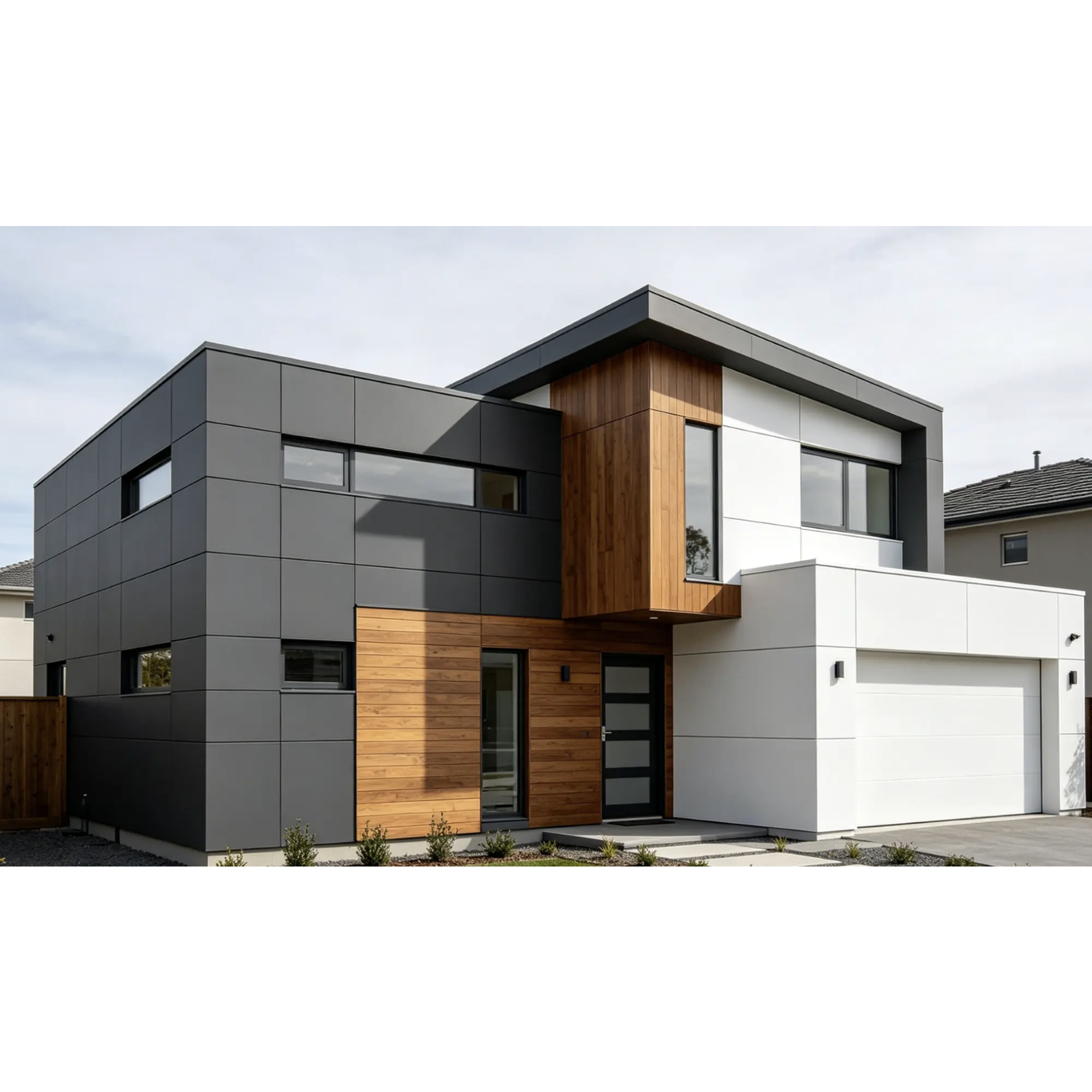
You stand back and admire the finished facade. The panels line up perfectly. The joints are tight. The finish is flawless.
Then summer arrives. The sun hits the building. You see them. Raised bumps spread across the panel surface. The sleek facade now looks damaged.
What happened? Thermal expansion. The panels moved. And the fixing system did not let them.
This guide explains why floating joint systems are the proven solution to thermal expansion blisters. You will learn the physics behind thermal movement. You will understand how rigid fixing creates blisters. And you will know exactly how floating systems prevent them.
The Physics: Why Alucobond Moves
Alucobond expands and contracts with temperature changes. The linear thermal expansion coefficient is 2.4 mm per meter of panel length for every 100°C temperature difference.
In plain English:
A 1-meter-long panel expands by 2.4 mm when its temperature rises by 100°C. A 4-meter panel expands by nearly 10 mm. A 6-meter panel expands by over 14 mm.
For a real-world example:
Take a 3-meter panel. The expected heating of the panel is approximately 70°C (measured on a black panel at an air temperature of 40°C). With an assembly temperature of 20°C, the temperature difference is 50°C. Total expansion: 3.6 mm.
The calculation is straightforward:
2.4 mm × 3 (meters) × 0.5 (50°C temperature difference) = 3.6 mm total expansion
Half of that expansion (1.8 mm) must be expected on each panel edge.
If you do not allow for this movement, the panel cannot expand. Stress builds. The adhesive bond between the aluminum skin and the core is stressed beyond its limit. Voids form. Blisters appear.
Rigid Fixing: The Blister Creator
When you lock a panel down rigidly at every attachment point, you create a problem. The panel wants to expand. The fasteners say no. The stress has nowhere to go.
What happens with rigid fixing:
- The sun heats the panel. The aluminum expands. The polyethylene core expands even faster.
- Rigid fasteners prevent outward expansion. Stress builds inside the panel.
- The adhesive bond between the aluminum skin and the core is overloaded.
- The bond fails. Voids form. Blisters appear.
Poor planning of thermal expansion is one of the most common mistakes with Alucobond. Not taking expansion into account can cause deformations and cracks in the installation.
The evidence:
When panels are installed without allowance for thermal movement—often pushed tight against each other—the results are predictable. The metal warps, pillows, or oil-cans as it heats up and expands.
Floating Joint Systems: The Solution
Floating joint systems solve the problem by allowing the panel to move. One fixed point anchors the panel. All other attachments slide.
How floating systems work:
- Each panel has one "dead fix" (fixed point), usually positioned centrally
- All other fixings feature oversized or slotted holes
- The panel can expand and contract freely in every direction from the fixed point
- Stress does not build up. The adhesive bond is not overloaded. Blisters do not form
The key principle:
"To avoid any tension occurring in the rivet and screw connections, the rivets and screws must be set tension-free. The bore holes in the panels must be large enough to allow for the expected thermal expansion".
A professional Alucobond supplier will provide technical documentation on floating fixing systems. A manufacturer of Alucobond specifies these requirements in their installation guidelines.
The Hole Size Rule
The hole in the panel must be large enough to allow for expansion. If the hole is too small, the panel cannot move. The stress transfers to the fasteners. The panel buckles or blisters.
The rule from ALUCOBOND technical guidelines:
"With the shaft of the rivet fitting closely to the edge of the hole, the attachment head must cover over 1 mm of the area surrounding the hole".
What this means in practice:
Component | Requirement |
Hole in the panel | Large enough for expected expansion |
Rivet shaft | Fits closely to the hole edge |
Attachment head | Covers at least 1 mm beyond the hole |
Drilling method | Centrally drilled using multi-step drills or sleeves |
Caption: Hole size requirements for Alucobond floating joint systems. Source: ALUCOBOND processing guidelines.
Alt text: Table showing hole size requirements including panel hole size, rivet shaft fit, attachment head coverage, and drilling method.
Additional hardware:
Rivet attachment jigs are used for fitting blind rivets without jamming, allowing for a tolerance.
Fixed Points and Sliding Points
A proper floating system uses two types of attachment points:
Fixed points (FP): One per panel. Usually positioned centrally. This point anchors the panel. All expansion occurs outward from this point.
Sliding points (SP): All other attachments. Feature oversized or slotted holes. Allow the panel to slide freely as it expands and contracts.
What the guidelines specify:
"For fixing the supporting sections, pay attention to fixed point holders (FP) and sliding point holders (SP)".
Expansion Gaps: Making Room for Movement
Floating joint systems require adequate gaps between panels. The minimum gap depends on the expected expansion of the panel.
Guidelines for expansion gaps:
- For a 3-meter panel: allow at least 3.6 mm total movement (1.8 mm per edge)
- For larger panels: calculate using the 2.4 mm/m/100°C formula
- For runs exceeding 6 meters: physical expansion joints are required
Additional considerations:
- The total expansion must be accounted for when mounting panels on aluminum substructures transverse to the direction of the supporting section
- At least the total expansion must be accounted for when mounting on wooden substructures
- A reduced temperature difference of 10°C may be expected parallel to the direction of the supporting section
Installation Best Practices for Floating Systems
1. Drill centrically
"Holes in the panel and in the substructure must be drilled centrically (use drilling jigs)".
2. Maintain proper distance
"The distance between the panel and the rivet head should be 0.3 mm (use rivet attachment jigs)".
3. Do not over-tighten
"Be careful not to over-tighten the screws on the panel". Over-tightening locks the panel in place. It cannot move. It blisters.
4. Align substructure joints
"Arrange the butt joints of the supporting sections at the panel joints to avoid jamming due to opposing thermal expansion".
5. Follow system-based installation
ALUCOBOND panels are supported by proven fixing systems and technical expertise, ensuring precise alignment, controlled panel movement, and long-term durability.
The Floating System Flowchart
Start
│
▼
Calculate expected thermal expansion
│
├─── Panel length × 2.4 mm/m/100°C × temperature difference
│
▼
Design one fixed point per panel (central)
│
▼
Design all other attachments as sliding points
│
├─── Oversized or slotted holes
├─── Allow movement in all directions from the fixed point
│
▼
Drill centrally using drilling jigs
│
▼
Install with rivet attachment jigs
│
├─── Maintain 0.3 mm distance between panel and rivet head
├─── Attachment head covers 1 mm beyond the hole
│
▼
Leave adequate expansion gaps between panels
│
▼
Do not over-tighten fasteners
│
▼
Inspect for proper movement
│
▼
Done ───► No thermal expansion blisters
What to Ask Your Professional Alucobond Supplier
When you work with a professional Alucobond supplier, ask these questions:
1. What floating fixing system do you recommend? A knowledgeable manufacturer of Alucobond will specify fixed points and sliding points.
2. What hole size do you recommend for thermal expansion? The hole must allow for expansion—the attachment head must cover at least 1 mm beyond the hole.
3. What expansion gap do you recommend? The minimum gap depends on the expected expansion of the panel.
4. Do you provide rivet attachment jigs? These prevent jamming and allow for proper tolerance.
5. What is your thermal expansion coefficient? The answer should be 2.4 mm/m/100°C.
A reliable wholesale supplier of Alucobond will have technical documentation on floating fixing systems. A distributor of Alucobond panels should provide installation guidelines that include fixed point and sliding point specifications.
The Bottom Line
Rigid fixing creates blisters. It locks the panel in place. The panel cannot expand. Stress builds. The adhesive bond fails. Blisters form.
Floating joint systems prevent blisters. One fixed point anchors the panel. All other attachments slide. The panel expands and contracts freely. Stress does not build. The bond holds. The panel stays flat.
The physics is clear: Alucobond expands at 2.4 mm per meter for every 100°C temperature change. A 3-meter panel in a 50°C swing moves 3.6 mm. Without room to move, that force causes blisters.
Prevention is straightforward:
- Calculate the expected expansion for your project
- Design one fixed point per panel (central)
- Use sliding points with oversized holes for all other attachments
- Drill centrically using jigs
- Maintain a 0.3 mm distance between the panel and the rivet head
- Leave adequate expansion gaps
- Do not over-tighten fasteners
A professional Alucobond supplier provides the technical documentation. Your installation process determines the quality. Get the fixing system right, and your facade stays flat for decades. Get it wrong, and the blisters appear on the first hot summer day.